Technical background, development, car chassis and key data of the C29 racing car.
Technical background C29 – Steering wheel
The steering wheel in a Formula One car is the driver’s control centre. From here he steers the car, operates the clutch, changes gear and can adjust any number of electronic functions using several buttons.
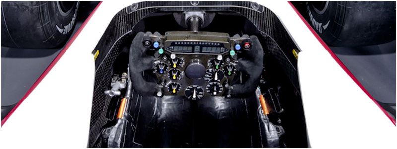
The first stage of the design process sees the engineers set out the functions which the driver will control using buttons or rotary switches. The initial layout is then established, before a provisional version of the steering wheel is made using rapid prototyping. In the next stage, the driver is brought in to assess whether all the controls are in the optimum position. If this is not the case, he expresses how he would like them to be.
Manufacture of the definitive steering wheel can now begin, for which the carbon-fibre “frame” provides the basis. The holes for the switches and buttons are bored into the frame before the foam for the grip is applied. This is then wrapped in carbon fibre once again. The finishing process sees the application of various materials to cover the steering wheel. Depending on driver preference, it can be lined with leather or shaped to the hands using a silicon mass.
Now it is time for the buttons and switches to be added and wired up to the circuit board before the display is connected. Since 2008 both the circuit board and the display form part of the SECU and are available in standardised form by the FIA.
After all the electronics work has been completed, the specialists set about assembling the mechanical parts – such as the gearshift and clutch paddles – and the quick release mechanism on the reverse side of the wheel. Drivers removing the steering wheel to get in and out of the car and then replacing it has become a familiar sight to F1 fans. The quick release mechanism is also required to pass an FIA test in which the driver has to be able to vacate the cockpit within five seconds.
Before the steering wheel is sent into action it is checked over on the test rig. Only when it has emerged from this testing session with flying colours are the buttons and switches glued onto the reverse side of the frame. It may weigh just one kilo, but this lightweight high-tech steering wheel is now ready for some seriously heavy use.
Technical background C29 – Carbon fibre
With the exception of the engine, gearbox innards and wheel carriers, a Formula One car is made almost exclusively from carbon fibre. High rigidity and strength, coupled with very low weight, are the stand-out attributes of carbon. It boasts a similar level of rigidity to steel, but is around five times lighter. On the downside, the manufacturing processes involved in making it are highly complex and its material price is considerable. One square metre of pre-impregnated carbon-fibre sheeting costs between 50 and 200 euros.
Carbon fibres have a diameter of five to eight micrometres. Typically, between 1,000 and some 20,000 fibres are brought together into bundles, and these are woven into textile-like structures.
Around 20 different types of carbon-fibre material are used in Formula One. These differ most prominently from one another in their structure and the type of resin with which they are impregnated. Should the forces only be coming in from one direction, unidirectional layer is used. If they are being exerted from various different directions, on the other hand, bidirectional weave is preferred. In order to provide the properties desired, specialist composite engineers establish which weave is required, in which resin and in how many layers.
The manufacturing process involved in making a carbon-fibre part incorporates several stages. First the part is designed using computer-based CAD (Computer Aided Design) techniques. This data is then refined and provides the basis for CAM (Computer Aided Manufacturing). The mould is cut into a tooling block on a five-axis milling machine; this block serves as the positive mould. The laminators place the precisely pre-cut carbon-fibre pieces one after the other onto the tooling block following plans drawn up by the composite engineers. When this stage has been completed, the whole item is packed into a polythene bag, vacuumised and cured for anything between ten and 20 hours in the autoclave at a temperature of around 50 degrees Celsius. After some final touches, the negative mould is then ready to be manufactured into the carbon-fibre part itself.
The laminators lay the pre-moulded carbon-fibre pieces on top of and along-side each other in the negative mould. Depending on the part in question, this can involve as many as several hundred pieces. When everything is ready, the mould – plus carbon-fibre inlay – is also packed into a polythene bag, vacuumised and cured for five to six hours at a temperature of approx 150 degrees. When the curing process is over, the individual parts are further refined and brought together into finished components. A front wing, for example, consists of around 20 separate carbon-fibre parts. Components which need to demonstrate particular toughness are made with Kevlar as well as carbon fibre or Zylon.
Technical background C29 – Seat
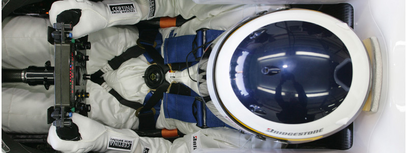
The latest Formula One cars endure lateral acceleration of over 4g through corners and as much as 5g or more under braking. An F1 race will see these forces exerted on the driver repeatedly over a timeframe of one-and-a-half to two hours. A perfect seating position for the driver is absolutely vital, since the smallest pressure points can lead to pain or muscle cramp. Each driver, therefore, uses a seat which has been tailored precisely to his measurements.
The manufacture of a new seat is based around a basic carbon-fibre shell, which is lined with a polythene bag. This contains either a two-component foam or polystyrene granules, which are then vacuumised. The driver sits in the seat and waits as this mass slowly moulds itself to his body. At the same time, a steady stream of small modifications are being carried out. The position of the steering wheel and pedals are also adjusted. When everything is in the right place, the seat foam or polystyrene granules are left to harden. A seat fitting of this nature will occupy the drivers from half up to a whole day. The end result is a transitional seat which will be used for initial testing and serve as a prototype for the final version.
The definitive seat is made by first electronically scanning the inner surface of the provisional model. The engineers use the scan to create a mathematical surface, on the basis of which the form is moulded into a tooling block. The seat then takes shape through the application of individual carbon-fibre sheets and is cured in the autoclave.
The final manufacturing stage sees the seat given its finish. As part of this process, the apertures for the safety and rescue belts are cut out and a one-millimetre-thick layer of padding added. A finished seat weighs around three kilos.
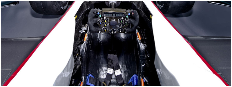
Technical background C29 – Monocoque
The monocoque is the core of a Formula One car, the driver’s workplace and survival cell in one. The engine is flanged on at the rear, the car’s nose at the front. The form of the monocoque is shaped by a series of factors, such as the car’s wheelbase, the size of its fuel tank, the driver’s physique, and aerodynamic requirements.
The first stage in the design process for the monocoque involves the definition of the surface form. Finite-element calculations are then carried out in order to ensure that the safety cell meets the levels of rigidity and strength identified as necessary by the engineers. These requirements are based on the dynamic loads encountered by the car on the one hand, and the safety stipulations of the FIA on the other. The safety standards underpinning the construction of F1 cars have risen constantly over recent years and passive safety for the drivers has, therefore, improved significantly. To this end, the key tests are the frontal crash (with nose section) at a speed of 15 m/s, the side-on impact at 10 m/s and the stationary load test for the roll-over bar, which has to withstand some twelve tonnes of pressure. A total of five dynamic and ten stationary tests are carried out on the car overall.
The monocoque consists of a carbon fibre/aluminium honeycomb composite. This combination produces extremely high rigidity and strength, yet keeps a lid on weight. The composite engineers work out how many layers of carbon fibre are required in which areas in order to meet the diverse demands placed on the car. In so doing, they can also choose from various different types of carbon fibre, depending on whether forces are exerted from only one direction or from several. In areas subjected to particularly heavy loads, up to 60 layers of carbon may be stacked on top of each other. A monocoque consists of a total of around 1,500 individual carbon-fibre pieces.
It is made from two half shells, into which additional strengthening elements are glued. After several curing stages in the autoclave the half shells are glued together. The final stage involves the assembly of numerous securing components.
Its enormous strength allows the monocoque to offer the driver an extremely high level of protection even in major impacts. And because the fuel tank is also contained within this structure, dramatic fireballs caused by accidents are a thing of the past. The safety cell can almost always be repaired following a crash.
The Hinwil based team produces some four to five monocoques per year to be used in races, track testing and on the test rig. Every single safety cell must be homologated by the FIA, although only the first example has to pass the full quota of tests.
Car – Data C29
Key data
| Chassis | Carbon-fibre monocoque |
| Suspension | Upper and lower wishbones (front and rear), inboard springs and dampers, actuated by pushrods (Sachs Race Engineering) |
| Brakes | Six-piston brake callipers (Brembo), carbon pads and discs (Brembo, Carbon Industries) |
| Transmission | Ferrari 7-speed quick shift gearbox, carbon, longitudinally mounted, carbon-fibre clutch |
| Chassis electronics | MES |
| Steering wheel | Sauber Motorsport AG |
| Tyres | Bridgestone Potenza |
| Wheels | OZ |
| Dimensions | Length 4,940 mmWidth 1,800 mmHight 1,000 mmTrack width, front 1,495 mmTrack width, rear 1,410 mm |
| Weight | 620 kg (incl. driver, tank empty) |
Key data Ferrari 056 Engine
| Type | Naturally aspirated V8, cylinder angle 90 degrees |
| Cylinder block | Sand cast aluminium |
| Valves / valve train | 32 / pneumatic |
| Displacement | 2.398 cc |
| Bore | 98 mm |
| Weight | > 95 kg |
| Electronic injection and ignition | |
Car Chassis C29 – Requirements and development
At first glance the most important new technical and sporting changes for the 2010 season do not seem so major at all. Refuelling during the race is now banned and the cars’ front tyres must be around 25 millimetres slimmer. So far, so good. However, these apparently minor tweaks have extremely far-reaching consequences. The refuelling ban means each car’s fuel tank now needs to be almost twice as large as before, and the narrower front tyres require very different weight distribution.
Bearing this in mind, the designers had carried out initial calculations as early as February 2009 using computer-aided flow simulation. This involved examining the effects of the slimmer tyres and longer wheelbase before starting work on the concept for the car in April 2009.
The fuel tank of the 2009 car had a capacity of between 120 and 140 litres, and that has now had to be increased to around 200 litres. This has led to significant changes in the dimensions of the monocoque, making compromise unavoidable. The regulations limit the width of the car to 1800 mm, while space also has to be made for the radiators. These must be integrated to produce maximum aerodynamic effect and allow optimum airflow. Positioning the fuel tank any higher is not advisable, as this would also raise the car’s centre of gravity. This means that the tank’s length has been expanded chiefly to create the extra capacity required. The knock-on effect on the car’s total dimensions sees roughly 20 centimetres added to both its wheelbase and overall length.
Another important consideration is how the distribution of weight through the car will alter during the course of a race. The engineers’ aim is to ensure that weight distribution remains as constant as possible despite obvious changes in fuel load. The rise in the cars’ minimum weight – from 605 to 620 kilograms – and higher fuel loads at the start of a race mean that the overall grid weight of the cars will be around 80 to 90 kg higher than before. That will also lead to lap times falling by up to five seconds over the race distance.
Car Chassis C29 – Engine and gearbox
The adoption of a Ferrari engine and gearbox presented the engineers with another challenge. However, the linking with their counterparts in Maranello has run very smoothly from the start, allowing the switchover to pass off without any notable problems or delays. The standard engine electronics also slotted in well with the engineers’ designs and made a comparatively easy fit with the characteristics of the Ferrari powerplant.
Much more significant was the impact of the gearbox, which includes the inner mounting points for the rear suspension and therefore partially dictates the car’s kinematics.
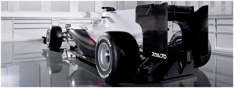
Car Chassis C29 – Aerodynamics and form
The 25 mm narrower front tyres require weight to be shifted further back in the car. And so, in order to guard against an excessive tendency to understeer, the car’s aero characteristics have to be adjusted accordingly.
When it came to the C29’s aerodynamics, the engineers have benefited from a development programme for the F1.09 which continued almost to the last race of 2009 – and underpinned a considerable increase in performance. Although the narrower front tyres and extended wheelbase gave the aerodynamics experts a different platform on which to work, they were still able to build on the knowledge gained with the 2009 car. With winter testing not permitted until 1st February, this provided them with a particularly significant edge. Indeed, for the engineers the final races of last season doubled up as opportunities for testing.
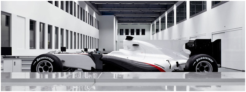
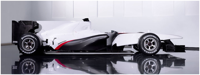
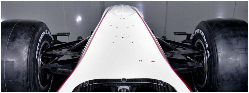
From the side view the highly intricate raised nose of the C29 is eye catching. Also clearly visible is the extremely long undercut at the transition from chassis into underbody. This solution, which turned out to be the most promising variant during the development phase, allows a particularly high quantity of air to be channelled to the underbody and therefore the double diffuser.
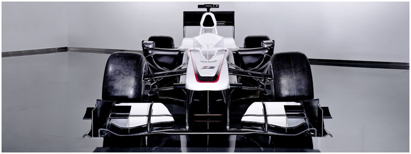
The front wing is a totally new construction, but is based in concept on the previous year’s design. Here again, the engineers had already successfully employed various technical solutions on race weekends in 2009.
Small, raised air intake apertures in the sidepods allow an extremely defined undercut. Their effect is complemented by the turning vanes positioned in front of them. These measures also help to optimise airflow to the underbody and lower rear wing.
The larger fuel tank also has an effect on the engine cover, of course. The length of this section, too, has been increased and it is heavily undercut at the rear. Extremely close-fitting exhaust pipes help to make this form possible. Here, slimmer design enables extremely effective airflow to the rear wing and upper section of the double diffuser.
It goes without saying that the design of the C29 focused squarely on the use of a double diffuser from the outset. The full spectrum of possibilities permitted by the regulations have been exploited to impressive effect, with the aerodynamic efficiency of the car as a whole significantly improved.
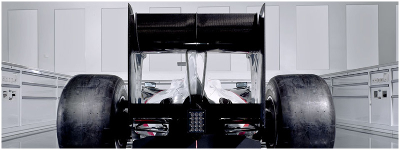
The rear wing represents a further development of last year’s version and retains the same central support construction.
Car Chassis C29 – Suspension and materials
Substantial changes have been made to the front suspension concept, the lower wishbones in particular being set a good deal higher than before. This arrangement was prompted by the modified monocoque. Another totally new feature of the front axle are the brake vents, which now have two air intake apertures each in response to the higher car weight and consequent increase in braking energy. Wheel rim shields are no longer permitted by the regulations.
The use of Ferrari’s carbon gearbox played a key role in the design of the rear suspension, as the inner pivot points were already decided by the architecture of the gearbox casing. The car’s overall weight (up to 90 kg greater than in 2009 with a full tank of fuel) was a factor in setting the kinematics. The aim is to make the car as easy as possible on the tyres, which will be placed under severe loads – especially when the car is heavily fuelled.
Of course, the C29 also incorporates the changes to the regulations aimed at cutting costs. For example, the wheel carriers are no longer made from the eye-wateringly expensive MMC (Metal Matrix Composite) widely used previously, and exotic alloys are no longer permitted for the wheel rims either. Their dimensions, furthermore, are precisely defined, removing any scope for the teams to experiment with marginal differences in rim widths.
Courtesy Sauber Motorsport © RIF